Introduction and Motivation
During my gap year, I aimed to improve my engineering skills through a project which would challenge both my theoretical understanding and practical capabilities. I wanted to have a better grasp of control systems due to my curiosity and their intensive use in the aerospace industry.
I had an old Segway-style scooter called Smart Balance Wheel, also known as a hoverboard, and I decided to build another one from scratch. The platform has two wheels in total located on both sides of the rider, making the platform inherently unstable. Without the use of active stabilization algorithms the platform can not stand up right. This was a totally new concept for me; I have experimented with simple feedback control loops but never with an unstable system. This fact gave the project the complexity I was searching. In addition, I wanted to experiment with the control input, changing it to a center of gravity driven system. The board would react based on where the riders center of gravity was, instead of light sensors used in my Smart Balance Wheel.
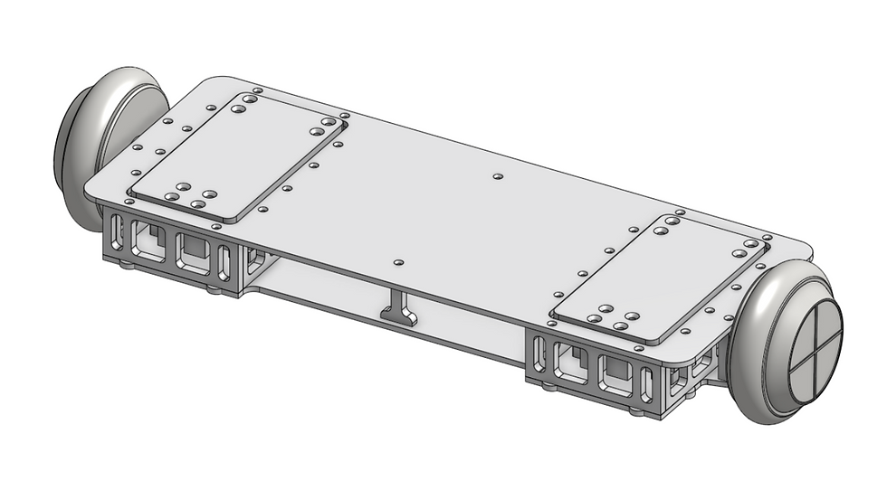
System Overview
The hoverboard operates on a closed loop system. The rider’s weight distribution is measured by the load cells, while inputs such as orientation, rotational state and acceleration are measured by the IMU. Hall sensors also contribute to the control loop providing information regarding wheel rotation and speed. The microcontroller then calculates the appropriate action based on these measurements and sends a command to the motor drivers. Then the drivers communicate with the motors independently to achieve the required motion. This process is repeated continuously to maintain dynamic balance and to fulfil the rider’s commands.

Mechanical Design
Load Cell Configuration
I arrived at this configuration to minimize the probability of errors during the center-of-gravity calculations. Ideally, the pressure plate should be larger than the rider’s feet, with the load cells positioned outside the areas where the rider’s feet apply pressure.
This configuration provides two main advantages. First, it allows the system to measure larger loads. Second, it reduces the effect of small shifts in the rider’s pressure distribution on the calculated center of gravity. This is because the load cells have a longer lever arm relative to the rider’s pressure points.
In contrast, if the rider’s support points were located farther from the center of the pressure plate than the load cells, even small shifts in pressure could produce larger loads at the sensors due to torque. This could amplify changes in the load measurements and potentially saturate the load cells.
A larger pressure plate also ensures that the rider’s feet remain within the area covered by the load cells when mounting the device. This helps maintain reliable measurements regardless of where the rider initially places their feet.

Pressure Plates
Given the facts above, I chose a plate with dimensions of 190 mm x 99 mm x 8 mm to keep the design compact and lightweight. I chose 7075 series aluminium as the pressure plate material due to its low modulus of elasticity and light weight I decided on the pressure plate dimensions based on a foot that measures 260 mm long, 100 mm wide in the toe box and 60 mm wide in the heel, which approximately corresponds to a size-41 shoe per the European system. Since the actual support points of a foot are shorter and narrower (approximately 150mm for the given sample) the 190mm length and the 99 mm width is sufficient for my chosen feet model. These plates also sit three millimeters higher than the upper plate, ensuring that even riders with larger feet would transfer their whole weight to the pressure plates. Thus, load cell measurement would stay unaffected. In terms of load cell placement, I located the load cells facing backwards inside of the ones facing forwards since the heel is narrower than the toe box; as such they could be located closer to each other without hindering the quality of the center of gravity calculations.
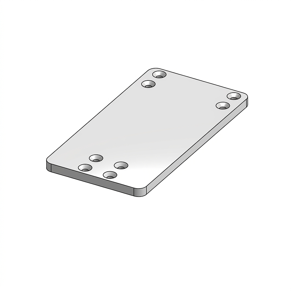
Load Cell Spacers
I added load cell spacers to create 10 mm of additional height in the electronics compartment. I needed more height in the electronics compartment because of the battery I planned on using. Since the load cells were going to be mounted on this piece to be rigid for accurate measurements, thus I decided on 7075 aluminium as the material of choice. This extra space between the load cells and the bottom plate also benefited the motors. The power and Hall sensor cables needed to pass through the load cell compartment before reaching the electronics compartment. This space introduced a route where those cables could pass through without interfering with the load cells.
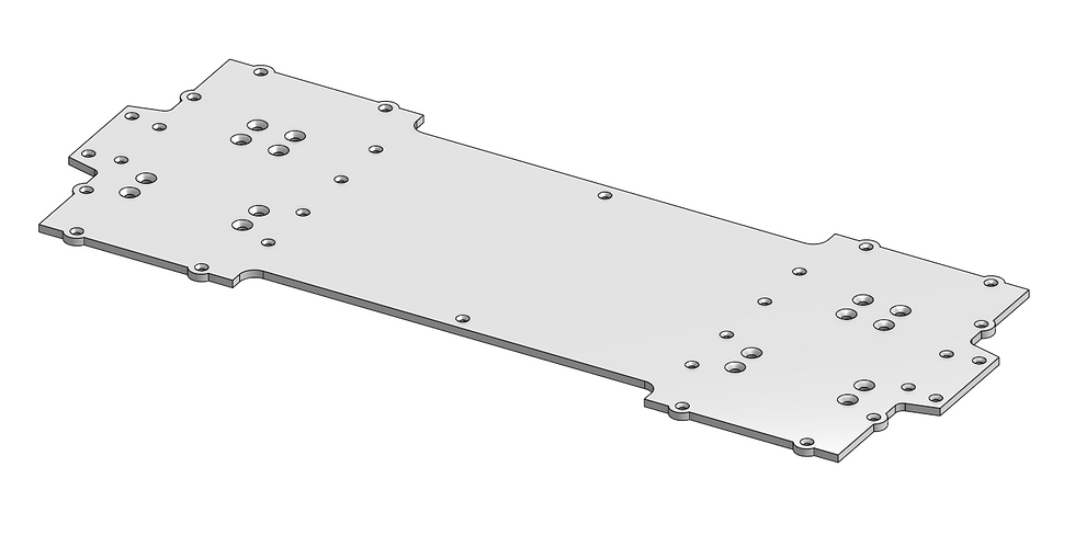
Bottom Plate
The bottom plate has the dimensions of 580 mm x 228 mm x 5 mm and houses all the other parts. I had previously decided on the material as 6061 series aluminium to better resist the bending forces. However, the supplier did not have 6061 series aluminium for the given thickness thus I ended up using 5754 aluminium.

Load Cell Compartment
I added walls around the load cells, creating a compartment to minimise bending and torsion under load, allowing more accurate data to be received from the load cells. I punched holes in these pieces to save weight without sacrificing too much strength. These holes also allowed cables to be fed through. I decided on the long sides of this compartment to be 7075 series aluminium with dimensions of 204 mm x 50 mm x 8 mm. The short sides of the compartment are identical to the long sides in terms of function and material, with the only difference being size: 129mm x 50mm x 8mm.


Motor Mounts
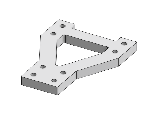
The purpose of the motor mounts is to create sturdy mounting points for the motors which are also the wheels. The piece has dimensions of 68 mm x 50 mm x 10 mm and is machined out of 7075 series aluminium. As can be seen in the photos below. I also included a photo of the mechanical drawing to better illustrate the parts shape with disections. I deliberately designed the motor shaft to be eccentric in order to increase the ground clearance. This allows for steeper tilt angles thus allowing the platform to climb steeper slopes. The current tilt angle with this configuration is 21 degrees according to my calculations. However, realistically the tilt angle will be lower to prevent the board’s edge from scraping on the ground. The tilt angle will also be limited with software for the balance loop to function as desired. For the platform to apply brakes, it needs to move ahead of the center of gravity and that can only be achieved by accelerating if the board is already cruising forwards at a given speed. For that reason, the top speed and tilt angle will be capped at a certain value.


Upper Plate
The upper plate is added as a cover on top of the board, it conceals the electronics compartment and helps with distributing the bending and torsion forces. I used 5754 series aluminium with dimensions of 580 mm x 229 mm x 5 mm due to the same reason I used 5754 aluminium for the bottom plate.

Electronics Compartment Supports
I added the electronics compartment supports to prevent the upper plate from caving in on the electronics compartment. They are located on the middle point of the 280 mm-long span between the two load cell compartments. I used 7075 series aluminium with dimensions of 50 mm x 30 mm x 10 mm for these pieces.


Components
Load Cells
For the load cells I decided to use the Keli AMIB C3 shear beam load cells with a capacity of 20 kg because they were already present at the laboratory. I decided to use eight load cells in total, four under each foot, giving me a total measuring capacity of 160 kg.


HX711 Amplifiers
The reason I integrated the HX711 module into my design is to receive readable output data from the load cells. The load cells alone output a very week analogue signal measured in millivolts. The HX711 module converts the output from the load cells to a higher voltage digital signal. This enables the controller to successfully read the incoming data. I used 8 HX711 modules in total, one for each load cell with the dimensions of 34 mm x 24 mm x 3 mm.
• Operating Voltage: 2.6V to 5V
• Output Voltage: Copies input voltage
• Operating Current: 1.5 mA
• Sleep Mode Current: < 1 µA

Internal Measurement Unit (IMU)
As the IMU I chose to use the MPU6050 module which combines a 3-axis gyroscope and a 3-axis accelerometer to track motion. The output rate on both the accelerometer and the gyroscope is 1 kHz which was sufficient for the balance loop.
• Operating voltage: 3.3V to 5V DC
• Operating Current: 4 mA
• Sleep Mode Current: 5 μA
• Communication: Standard I²C protocol

Teensy 4.1
For the microcontroller I used the Teensy 4.1 due to its speed and advanced features. The board has a powerful processor that runs at 600 MHz. It also features dedicated hardware for floating-point math. This feature allows the board to solve math equations that consist of the data type float approximately 200 times faster than regular boards. Teensy also has 18 analogue pins and 55 digital pins with interrupt capability which 35 of them having the option to be used as PWM outputs. And the dimensions are as follows 61 mm x 17.7 mm x 4.1 mm.
• Operating Voltage: 3.3 V
• Operating Current: 100 mA (excluding all external devices connected to the pins)
• Processor: NXP i.MX RT1062 ARM Cortex-M7
• Flash Memory: 8 MB
• RAM: 1024 KB

Hub Motors
I decided to use 3-phazed hub motors that were already present at the laboratory which also functions as the wheels. The motors are embedded inside the wheels as can be seen in the image below.
The motors were previously bought from a small company called Cansın Motors. Unfortunately, I could not find the exact modal at their site. For that reason, I could not get my hands on a datasheet concerning the motors. But I was able to get some specifications from other students reports whom used the motors before me and they are as follows.
• Voltage: 36 V
• Engine Power: 250 Watt
• Rated Speed: 450 rpm
• Speed without load: 150-1600 rpm
• Maximum Rated Current: 6A
• Rated Torque: 10 Nm
• Maximum Torque: 12.25 Nm
• Loading Weight: 108.9 kg
• Outside Wheel Diameter: 13.97 cm

Motor Drivers
Because 3-phase motors require specific phase sequencing, they cannot be operated by simply applying a direct electrical current. For that reason, I decided to use a motor driver. I chose to use the BLDC motor controller WS55-220 since it was present at the laboratory. The drivers were previously bought from a Chinese exporter called Bewinner. The specifications are as follows.
•Rated voltage: 20-50VDC
•Rated current: 10A
•Limited current: 12A
•Maximum speed: Over 20000 RPM


Power Supply
For the power supply we decided to use the Samsung Li-Ion Hoverboard Battery since it was already present at the laboratory. It allows high spontaneous current draw which is required for acceleration. It is also energy dense meaning the battery pack can stay relatively light weight while delivering sufficient power to the hoverboard.
The pack has the dimensions of 135 mm x 95 mm x 58mm and the specifications are as followed.
•Voltage: 36V
•Capacity: 3000mAh
•Continuous Discharge: 20A
•Peak Discharge: 30A
